Sector
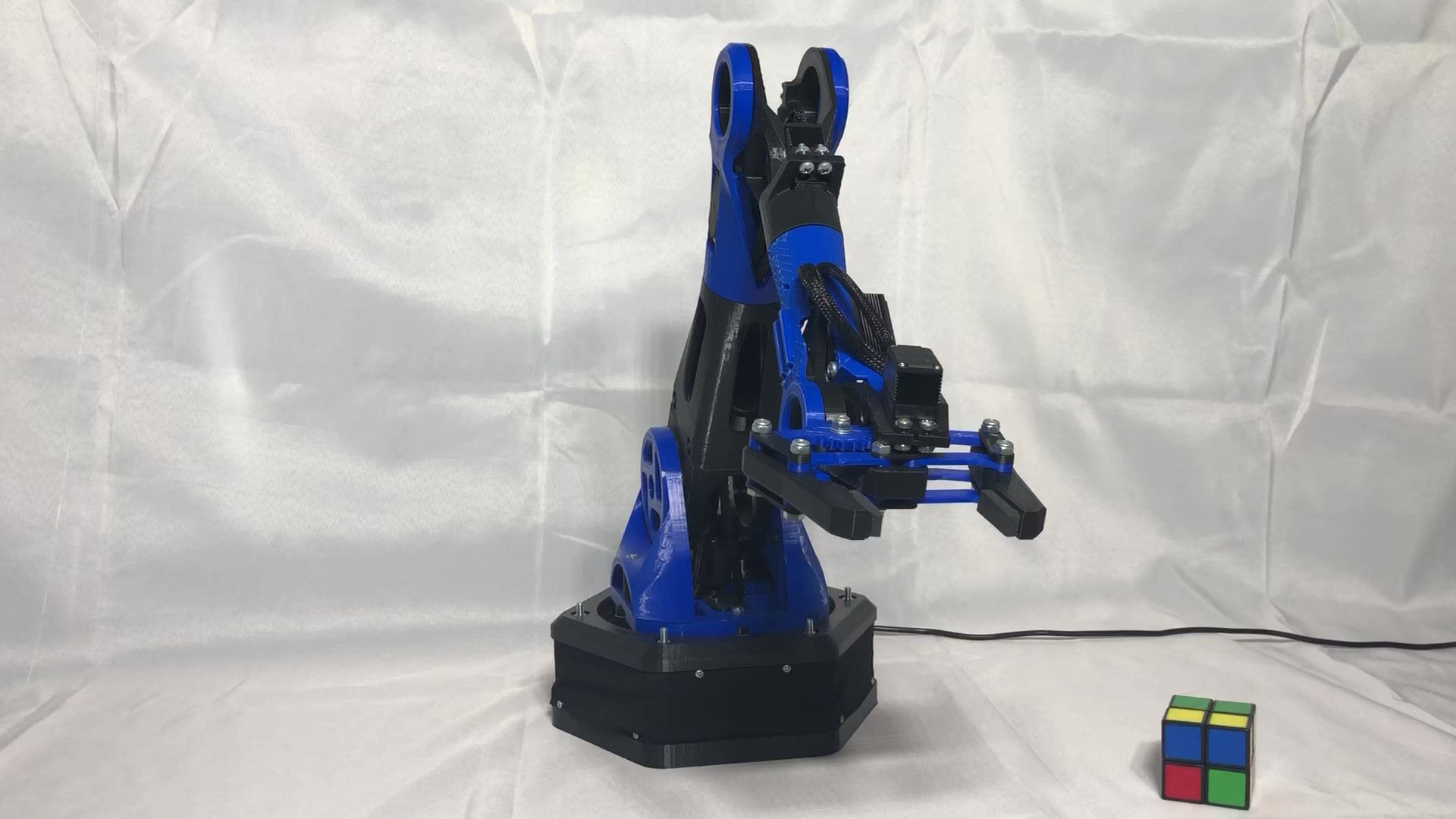
6DOF Robotic Arm

I began this project at the start of the CoronaVirus Pandemic. Stuck at home during summer, I was inspired to be productive with my time. Taking on this project thus was an exciting way to further my skills as a designer, inventor, and coder. I would like to make it abundantly clear that this project in no way is a kit of any kind. No one but youtube and internet research aided me to complete this project. Everything about this project is unique and personal. Almost every morning, I devoted 2-3 hours of time into developing this project. Starting with designs in CAD, I soon began printing and assembly, then electrical engineering, and finally coding. I ran into a lot of trouble on the way, often troubleshooting for hours. Several physical designs and code bugs had to be overcome. My determination and persistence got the project done in the end.
Full 6 Degrees of Freedom Demonstration
X,Y,Z Axis Movement
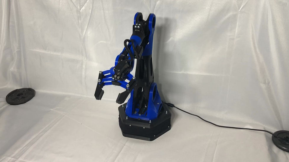
Constraints

Automated Claw Alignment

Claw Dynamics and Movement
Design
Interface
Electrical
Coding

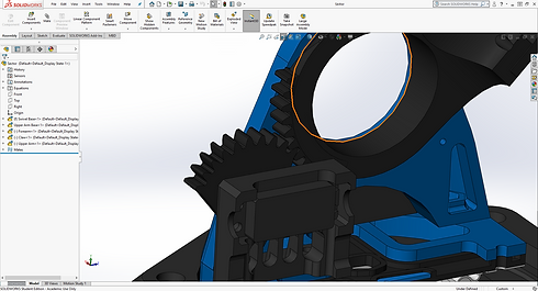
From an Idea to CAD
Engineering with Usability and Style
I began this project with only the idea in my head of what a robotic arm should look like. I was determined to design and create one myself, solely for the sake of experience in the field of engineering. When I started the CAD design, I envisioned making the joints hollow circles. This was both a cosmetic and useful design, acting as a plastic ball bearing. All parts on this arm were designed to be 3D printed, allowing for unique and complicated geometry. Gears with a 3:2 ratio allowed the servo motors to output more torque. A torrison spring was added to the arm that took stress off the main servo.

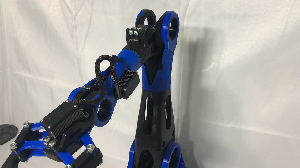
Wire Management
Engineering for Functionality
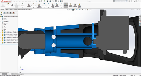
The “Forearm” of the robot was the most complicated assembly to design. Not only did it need to spin on the axis of the arm itself, servo wires needed to run though it. In the connected photo you can see a cutout of the “Forearm”. This interlocking system needed to perform two functions. First, it had to rotate while remaining structurally sound. It also needed an internal path for wires. A hole on the blue piece allows the wires to continue through the arm into the black piece. This integrated and complex system allowed the wires to be hidden internally even with a 120 degree rotation angle of the arm.

Prototyping
3D Printing and Part Iterations
My skills and experience have slowly matured with the projects that I have undertaken. Unlike previous projects where I redesigned and printed parts over 5 times, this project only required 1 or 2 part iterations. I contribute this efficiency to my experience using 3D printers as well as conceptual understanding and awareness in CAD. Complicated part geometries such as the one pictured were never overwhelming.
Assembly
SubAssemblies and Relations
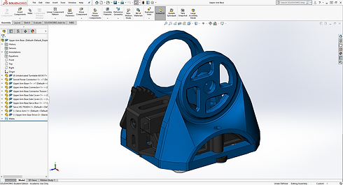
The following set of 5 photos shows the individual subassemblies of the robotic arm. Each subassembly refers to the main assembly for global variables, sketch relations, and geometry. M4 and M5 bolt holes are standardized across all assemblies. Global variables even exist within subassemblies to create efficient CAD designs. Creating assemblies in this manner allows for fast reliable updates and transformations to the entire robotic arm. I thus strive to design with these tactics to be as efficient as I possibly can.


Kivy Library
GUI Control Panel
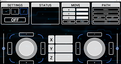
Of course with every robotic arm you need a way to control it. At first, and during its beta testing stage, I used a simple text console interface. This was not sufficient for controlling the robotic arm however and was never the end goal. Researching a possible GUI platform, I found the python library Kivy. Kivy is a complicated and well developed UI development library for python. Kivy is so complex, it even has its own kivy language, which I utilized to build the graphics of my interface. The interface includes buttons, toggle buttons, text inputs, statement reports as well as joystick inputs. Using the Kivy library, I also coded the logic alongside python.
Socket Library
Communicating Across Networks
The Kivy interface can be launched and operated on any device to control the robotic arm. This was made possible by use of the python socket library. The socket tutorials by Sentdex on youtube significantly aided my socket implementation. Sockets allow both the robot and interface device to send and receive messages across networks. The robot creates its own wireless hotspot, a standalone wifi network. The interface connects via IP address and a specified port. The socket sends string values, or keys, that specify what the robot should do and in what quantity. Most of the logic however, remains to be computed on the robot.


Packaging to Apps
EXE File and IOS App
In the connected photo, the interface is shown with the robotic arm. The interface is fully compatible with mouse and touchscreen inputs. It can be run on any device that has python installed. The interface has also been packaged to run on Windows without any dependencies. The user can simply activate the interface as easily as any other standard program. The Kivy library also easily allows the application to be packaged into an IOS platform. This means it could run on apple computers or a phone. Unfortunately however, I do not have access to a mac and therefore could not package this application for IOS.

Electronic Circuit
Motherboard, Regulators and Fuses
The motherboard is of course, my all time favorite Raspberry Pi. On top of the Raspberry Pi is a servo hat that easily connects the servos to the motherboard. Connecting the electrical components required soldering and the use of other electrical connections. Included in this electrical box are buck converters, or voltage step down regulators, fuses, a switch, and the motherboards. To create an organized layout, each group of electronic components easily separates, connected to its own side panel. All wires are heat shrink wrapped with standard connectors for easy and reliable assembly.
Power Supply
12V to 7.4V Operating Power
The electrical for this project was quite simple because there are no batteries. The simplicity of the circuit makes an eloquent outside appeal only showing a DC jack and power switch. The DC jack takes a 12V input. With buck converters, the voltage is brought down to 7.4 and 5.1 volts. Even though there are no batteries, the side of the robotic arm’s base is made of cloth to allow for cooling of the electronic components. The only part of this robot that was not created by me is this lining of the cloth around the base. My sister contributed by sowing this cloth.


Python ServoKit Library
Controlling Servos
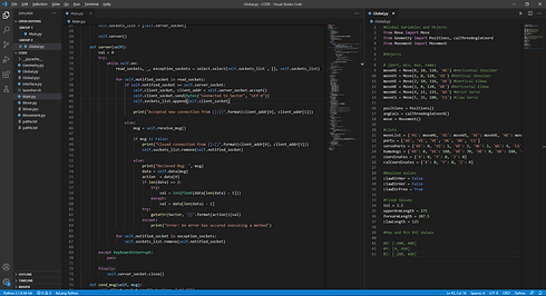
The Raspberry Pi Servo Hat comes with a very handy library that makes controlling the servos very easy. The ServoKit Library provided by Adafruit, takes angles as parameters that are then converted into PWM signals the servos can read and function off of. In the connected image, the modules, Move and Movement are displayed. These models are the class definitions the robotic arm uses for all 6 servos. Updating a servo position automatically performs logic, calculating servo angles and positions of the robotic arm.
Mathematical Movement
Geometry: Math Library
One of the most significant aspects of this code is its Geometry module, partly shown in a connected image. This module performs the necessary logic, calculating the position of the claw in respect to the origin. This requires trigonometry and the law of cosines. Moving the robot in this fashion allows it to maintain positions in the x, y, and z axes. It is also the logic behind leveling the claw in a horizontal and vertical position. This module allowed the user to specify a desired (x,y,z) point to reach as well as return the point the robot currently resides at.

Concise Code
Object Oriented Programming
Python is an object oriented language. I extensively used object oriented tactics in this project. Several instances of classes were utilized to control and calculate 6 servos. Inheritance also allowed my program to be concise when calculating positions. A module named Global served as a useful tool to store all class instances that could be accessible to other modules with a simple import. This project is by far the most concise, well developed and implemented code I've ever achieved. Although I consider myself a mechanical engineer, computer science, particularly with the python language is undoubtedly something I have taken a liking to and appreciation for.